
Connect wiring guide
Four simple steps to wire your SFPL CONNECT device. Follow the pictures — each step adds one connection.
Know your device
Look at these first so you can find the green terminal strip and pin groups before you start wiring.

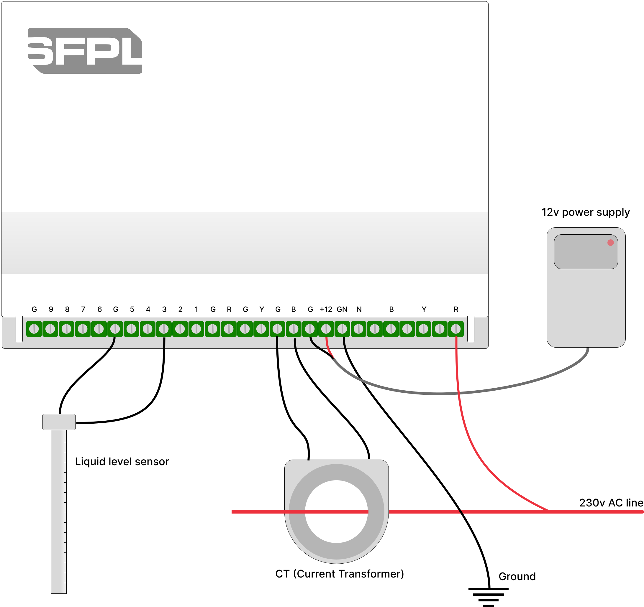
What you need
Gather these before you open the panel. Steps 2–4 are optional — only wire what you want to monitor.
- 12 V to 24 V DC power supply (adapter)
- Access to AC Neutral + 3 phases (if monitoring voltage)
- 3× CT clamps (if monitoring motor / pump current)
- Liquid level sensor (or other 0–30 V DC analog sensor)
- Screwdriver for the green terminal screws
Need exact voltage limits and pin counts? See the technical specification.
Connect 12 V to 24 V power
Give the device power first. Without this, nothing else works.
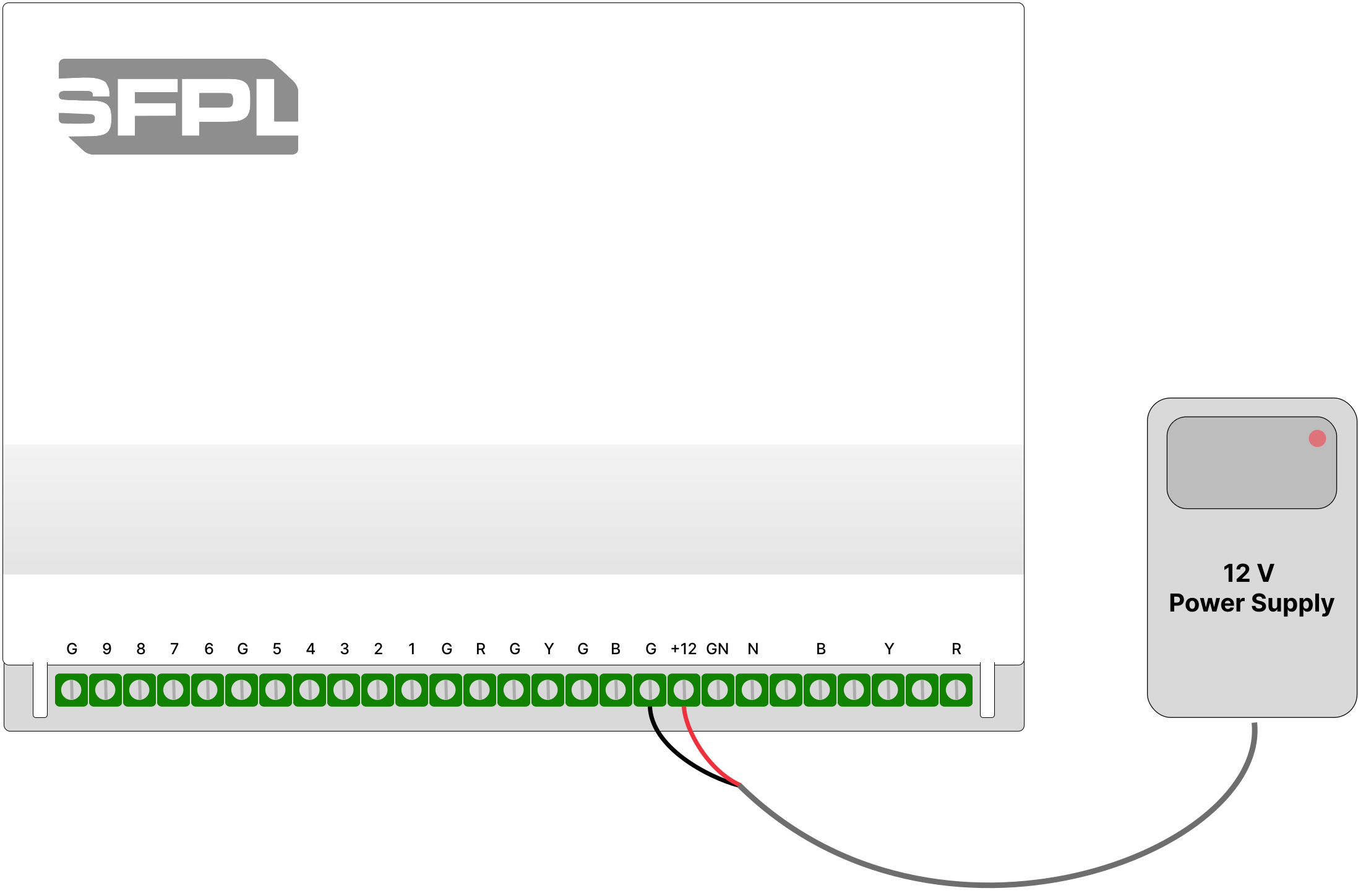
Figure 1 — Connect 12 V to 24 V power
- 1
Find the terminals
Look at the far right of the green strip — the last two screws are marked + and −.
- 2
Connect the adapter
Red wire → +. Black wire → −. Tighten both screws.
- 3
Check
This only powers the device. Do not use these pins to measure anything.
Connect AC voltage (optional)
Want to see if the AC supply is healthy? Wire Neutral and the three phases here.
Mains voltage — switch off / isolate the circuit before connecting. Qualified electrician only.
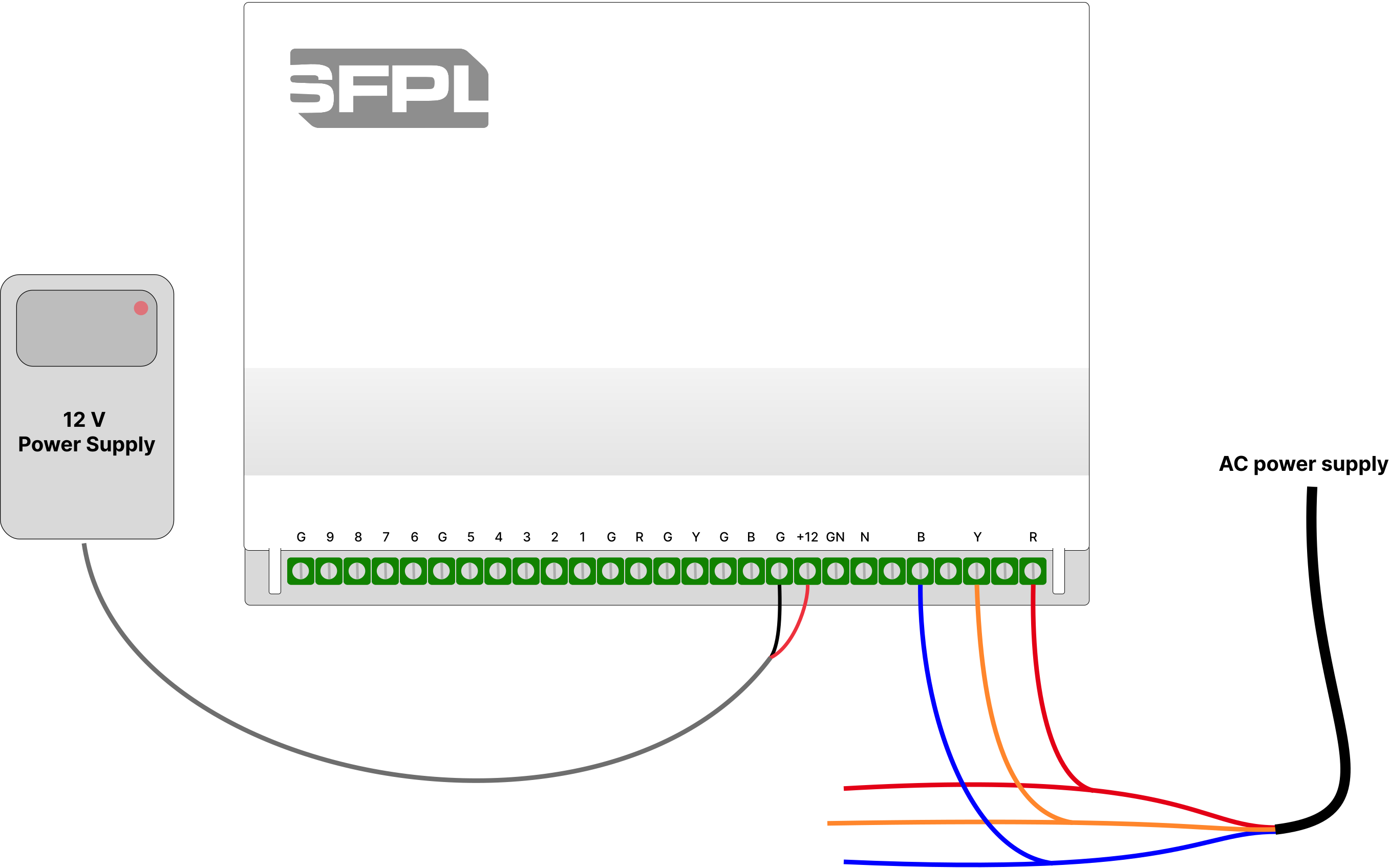
Figure 2 — Connect AC voltage (optional)
- 1
Keep power on
Leave the supply from Step 1 connected.
- 2
Match the labels
Connect Neutral to N, then Blue / Yellow / Red phases to B, Y and R.
- 3
What this does
Connect reads supply voltage (up to 300 V AC). It does not power the device.
Connect CTs for motor / pump current (optional)
To measure how much current a motor or pump draws, clamp CTs on its power cables.
Never connect mains / phase voltage into the CT terminals — only the small wires from the CT clamps.
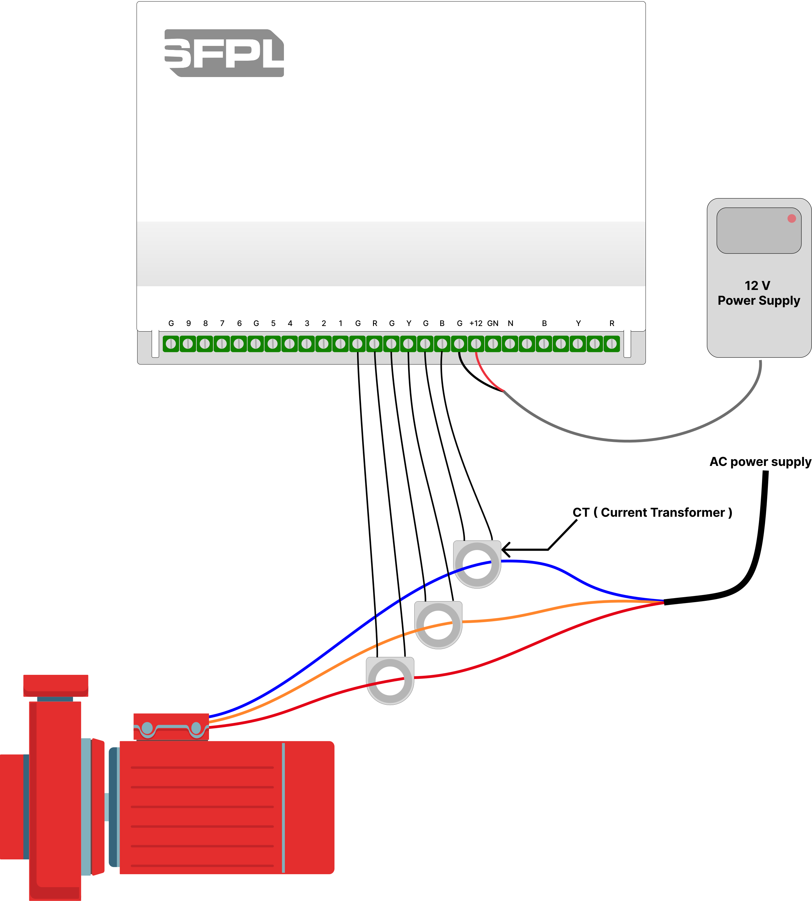
Figure 3 — Connect CTs for motor / pump current (optional)
- 1
Clamp the cables
Put one CT around each of the three phase wires going to the motor / pump (not around Neutral).
- 2
Wire the CT leads
Each CT has two thin wires. Connect all six wires to the current terminals in the middle-left group.
- 3
What this does
Connect reads current from the CT secondaries only (low voltage, max 5 V AC).
Connect a liquid level sensor (optional)
To monitor tank or sump level, wire a liquid level sensor to the analog inputs.
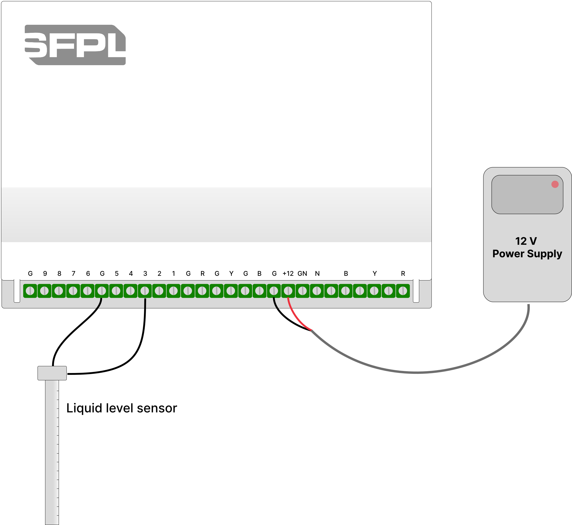
Figure 4 — Connect a liquid level sensor (optional)
- 1
Place the sensor
Install the probe in the tank / sump as the sensor maker recommends.
- 2
Connect two wires
Connect black wire to ground and red wire to any general purpose group (1-9) (voltage range: 0V - 30V DC).
- 3
In the portal
After power-up, open SFPL CONNECT and calibrate the channel (volts → level). Set alerts if needed.
Safety
- AC voltage (N / B / Y / R) is live mains. Isolate power and use a qualified electrician.
- CT terminals take only the thin wires from CT clamps — never phase / mains cables.
- Full ratings and pin map: technical specification. Help: Contact or FAQ.